We saw in Chapter 1 how real materials, in particular fluids, can be regarded as continuous if the distances over which their gross properties (like density) change is much larger than the molecular spacing. They can then be split up into small elements, to each of which the laws of particle mechanics can be applied. We have also set down those laws. Before applying them, however, we must know what forces act on such an element. As with the body sliding along the table (Fig. 2.7), the forces experienced by a representative fluid element are of two kinds, long-range and short-range.
The forces which act at long-range, the body forces, are experienced by all fluid elements; the two most common examples are gravitational and electromagnetic in origin. The electromagnetic force on an element depends on quantities like its electrical charge, but the gravitational force, i.e. the weight of the element, depends only on its mass; this is the only example of body force to be considered from now on. If a fluid element P which occupies the point x at a certain time t has volume V, and if the fluid in the neighbourhood of x at that time has density r* then the gravitational force on the element is rVg. [*Density is mass (kg) per unit volume (m3), and is measured in units kg m-3; the use of the Greek letter r to represent density is standard notation.]
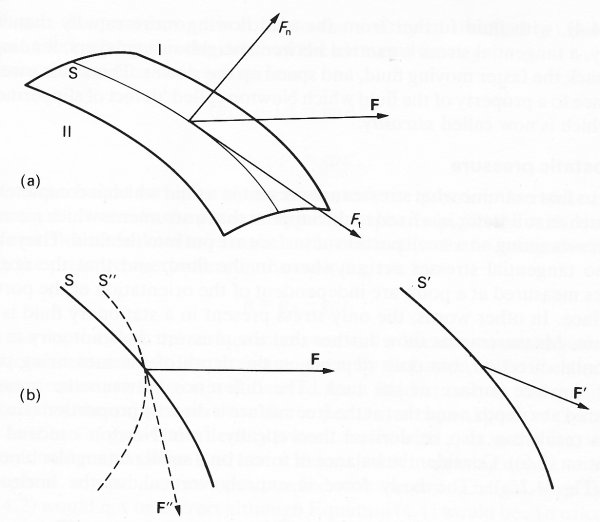
Short-range forces are exerted on the element P by those other elements with which it is in contact, and by no other. They consist of all the intermolecular forces exerted by molecules just outside the surface of P on the molecules just inside. If we consider a small portion of the surface of the element (Fig. 4.1 (a)),
Fig. 4.1. (a) A portion S of the surface of a fluid element, which we imagine to be drawn in the interior of the fluid. The sum of those forces exerted by molecules on side I of S on molecules on side II (such that their line of action crosses S) is F. F has components tangential to S (Ft) and normal to it (Fn). If S has area A, the stress exerted across it is F/A.(b) Side views of portions of surface such as S. The stress F'/A' exerted across a parallel portion S' (area A') at a different position in the fluid will normally be different from F/A. So will the stress F"A" exerted across another portion S" (area A") at the same location as S, but with a different orientation.
and add up all those forces exerted by molecules on side I, on molecules on side II, such that the line of action of the force intersects the portion of surface, the result will be a certain force F (a vector quantity, with a certain magnitude and direction). By Newton's third law, the force exerted by the molecules on side II on those on side I is equal to - F. The magnitude of F is proportional to the area A of the portion of surface; a quantity independent of A is the force per unit area, F/A, which is called the stress. The stress usually varies with both the position and the orientation of the portion of surface being considered. Consider, for example, a portion of surface S', with area A', parallel to the surface S, but centred on a different point of space (Fig. 4.1 (b)); the stress F'/A' acting across S' is usually different from the stress F/A which acts across S. Furthermore, the stress acting across a portion of surface S" (area A") centred on the same point of space as S, but with a different orientation (the broken curve of Fig. 4.1 (b)), is also usually different from F/A. We may note that, like the force exerted by a flat table on a body sliding over it (see Fig. 2.7, §2.4), the (stress) force F in general has two components, a normal component Fn, and a tangential component Ft (see Fig. 4.1 (a)).
In most of the flows which we shall consider, the important contribution to the normal stress is the pressure, which acts equally in all directions and is independent of the orientation of the surface portion considered. The tangential stress is analogous to the frictional force T (Fig. 2.7). It resists the relative motion of neighbouring layers of fluid, so if fluid is flowing over a plane surface (Fig. 4.4), with fluid further from the wall flowing more rapidly than that nearby, a tangential stress is exerted between neighbouring layers, tending to hold back the faster moving fluid, and speed up the slower. This stress owes its presence to a property of the fluid which Newton called 'defect of slipperiness', and which is now called viscosity.
Let us first examine what stresses are present in a fluid which is completely at rest, such as still water in a fixed tank. Suppose that instruments which measure the stresses acting on a small portion of surface are put into the fluid. They show that no tangential stresses act anywhere in the fluid, and that the normal stresses measured at a point are independent of the orientation of the portion of surface. In other words, the only stress present in a stationary fluid is the pressure. Measurements show further that the pressure does not vary in any horizontal direction, but does depend on the depth of the measuring point below the free surface of the tank. The difference between the pressure measured at a depth z and that at the free surface is directly proportional to z.
This result can also be derived theoretically, from Newton's second law (Equation (2.6)). Consider the balance of forces on a small rectangular block of fluid (Fig. 4.2 (a)).
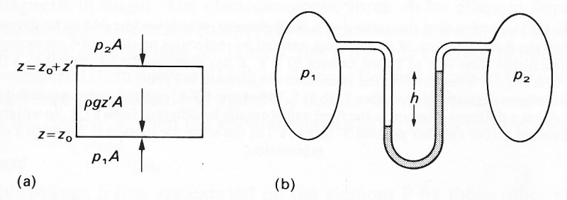
Fig. 4.2. (a) A small rectangular block of fluid, of vertical depth z' and horizontal area A, in equilibrium. The pressure forces on its sides must cancel out, so that pressure is independent of horizontal position. The vertical forces on the block (marked by arrows) must also balance, which leads to Equation (4.1). (b) The pressure difference p1-p2 between the two regions shown is measured by the difference in height h between the two arms of a U-tube containing a fluid of density r. In fact p1 - p2 = grh.
The body force is entirely vertical, so the horizontal components of pressure force must balance out, which implies that the pressure is independent of horizontal position, as observed. Pressure must, however, vary with height (the coordinate z) because there is no motion, and the weight of the element must therefore be balanced by an upward pressure force on the bottom which is greater than the downward one on the top. If A is the horizontal cross-sectional area of the element, and if p1, p2 are the pressures on surfaces 1 (the bottom) and 2 (the top) respectively (see Fig. 4.2 (a)), then the net upward force on the element is (p1 - p2)A. This must be equal to its weight, which acts downwards, and is equal to the density of the fluid (r) times its volume (Az', where z' is the depth of the element) times g.
Hence the force balance equation is
(p1 - p2)A = grAz'
or
p1 - p2 = grz'. (4.1)
Thus, as the height increases by an amount z', the pressure decreases by an amount grz'. If we take the pressure to be atmospheric (pA) at the surface of the tank, and choose the level z = 0 to be at that surface (so that z is negative in the fluid), the pressure everywhere in the tank is given by
p = pA - grz. (4.2)
As the depth below the surface increases, and z becomes more negative, so the pressure increases. The pressure given by Equation (4.2) is called the hydrostatic pressure, since it was derived for a fluid at rest. It can readily be checked that the units of pressure (force per unit area, or kg m-1 s-2) are the same as those of grz. If the density r itself varies with z, as in the sea, which becomes colder and saltier (and hence denser) with increasing depth, or in the atmosphere, which becomes more rarefied with increasing height, then Equation (4.2) would not be correct although Equation (4.1) would be. To calculate the pressure at some level, given its value at another level, we would have to add up the contributions grz' from each slice of thickness z' over which r was effectively constant.* [*If we divide Equation (4.1) by z', and take the limit in which z' tends to zero, we obtain
dp/dz = -gr (4.1a)
where the left-hand side is the rate of increase of pressure with height. Compare the symbol for 'rate of change with time' defined in Equation (2.1).] Equation (4.2) gives rise to the most commonly used method of measuring pressure. If two regions, containing gas, say, in which the pressures are different, are connected to the two arms of a U-tube containing a liquid of known density (Fig. 4.2 (b)), the levels of the liquid in the two arms will differ, by a height h. The pressure difference between the two regions is then immediately given by Equation (4.2) to be grh, where r is the liquid density. Two of the liquids most commonly used for pressure measurements are water (density 0.001 kgm-3) and mercury (density 0.013 kgm-3). This has led to pressures being quoted in units of cm H2O or mm Hg, referring to the equivalent height of a water or mercury column. However, since a mixture of units makes comparison of different pressures extremely complicated, we use the internationally accepted unit the Newton per square metre, or kg m-1 s-2. In terms of this:
l cmH20 = 98.l Nm-2
and
1 mm Hg = 133.3 Nm-2
(see Table 3.3).
A body immersed in fluid at rest in the earth's gravitational field experiences inwardly directed pressure forces over all of its surface. Because of the increase of pressure with depth, these forces are greater on the lower portions of surface than on the upper, and the net effect is an upward force called the upthrust. If the body is a cylinder with vertical sides and horizontal top and bottom surfaces of equal area A, then the upthrust is equal to the pressure difference between top and bottom, times A. If the height of the cylinder is h, we therefore have
Upthrust = grhA. (4.3)
But hA is the volume of the cylinder and rhA is the mass of fluid displaced by it, so the right-hand side of Equation (4.3) is equal to the weight of fluid displaced. That is, upthrust equals weight of fluid displaced, which can be shown to be true for bodies of general shape, and is a law first propounded by the Greek philosopher Archimedes. If the body is made of a material of uniform density r , the net force on it due to gravity (weight plus upthrust) is equal to the volume of the body times g times the density difference (r - r'). It is directed upwards if r is greater than r', and downwards if r is less than r'. Only when r equals r' does the body remain at rest with no net vertical force acting.
Let us now turn our attention to the stresses present in moving fluids. For this purpose it is convenient to consider the forces experienced by a small cubic element of fluid, and to suppose further that there is one direction in which the components of all the stress forces acting on the element always cancel out. The situation is therefore two dimensional, and all forces of interest act in the plane perpendicular to this direction: this is the plane of the diagrams in Fig. 4.3.
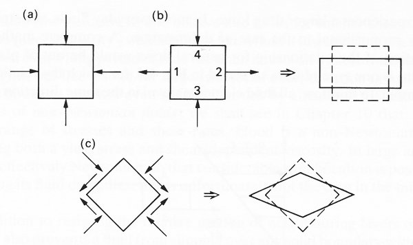
Fig. 4.3. Two-dimensional diagrams of the deformations produced in an incompressible cubic fluid element by stress-systems of the type indicated by the arrows, (a) No deformation associated with pressure on its own. (b) Equal and opposite tensile stresses on faces 1 and 2, together with equal and opposite compressive stresses on faces 3 and 4, result in the deformation shown on the right, (c) If the cube of (b) is tilted through 45°, the stress system then consists of a uniform pressure superimposed on tangential stresses in the directions indicated; these result in deformation as shown.
If the element were at rest in the absence of body forces like gravity, it would experience equal, inwardly directed normal stresses on each face, because pressure is independent of the orientation of the surface over which it acts (Fig. 4.3 (a)). These stresses would be in equilibrium, and would not tend to deform the cube in any way, apart from a uniform compression if the fluid were compressible; from now on let us suppose it to be effectively incompressible (see §4.6 for conditions in which this is permitted). A pressure, applied uniformly round the surface of a small fluid element in this way, can neither cause, nor resist, a change in shape of the element. However, if the normal stresses on the faces of the cube are not equal, they do result in deformation.
Now suppose that there are equal, outward, tensile stresses on a pair of opposite faces of the cube (faces 1 and 2 in Fig. 4.3 (b)), and equal, inward, compressive stresses on another pair (faces 3 and 4). Since the forces on opposite faces are equal, the element as a whole is not given an acceleration, and therefore its centre of mass remains at rest. However, a stress system of this nature would tend to deform the cube in the manner indicated in Fig. 4.3 (b). A similar deformation would result even if the stress were inwards on all faces, but of smaller magnitude on faces 1 and 2 than on faces 3 and 4; this would be equivalent to a uniform pressure with a system like that of Fig. 4.3 (b) superimposed on it. If the cube were tilted through 45°, as in Fig. 4.3 (c), it would tend to be distorted in the manner shown there, and the stress system then would consist of equal tangential stresses, superimposed on the uniform pressure. Thus either unequal normal stresses, or any tangential stresses, on the faces of a fluid element are associated with deformation of the element, and hence with motion. In a general motion, the element will be moved about bodily and rotated bodily as well as being deformed, but it is clearly only the deformations which can be associated with stress systems other than pressure.
As already indicated, all stresses other than pressure owe their presence to viscosity. We have seen in §2.4 that when two solid surfaces slide over each other, a resisting frictional force is set up. In the same way, when a body of fluid is set in motion in such a way that local deformation of fluid elements takes place, viscous stresses which tend to resist the deformation are set up. The magnitudes of the viscous stresses depend upon the rate of deformation. For example, when a body is moved rapidly through a fluid, it causes more rapid deformation of fluid elements than one moving more slowly. Therefore, the resistive viscous stresses which are set up are also greater, and the faster moving body experiences a larger drag force. In most everyday fluids, the stresses are directly proportional to the rate of deformation. A complete mathematical description of the relationship for general flows would be out of place here, but there is one type of flow, depicted in Fig. 4.4,
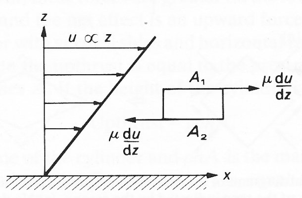
Fig. 4.4. Fluid flowing in the Jc-direction over a plane wall (z=0), with velocity u directly proportional to the distance z from the wall; i.e. the velocity gradient du/dz is uniform. The top surface A1 of the fluid particle shown experiences a forward tangential stress m du/dz', the bottom surface A2 suffers backward tangential stress of equal magnitude. The (forward) stress exerted on the wall also has the same magnitude.
for which the relationship is very simple. In this flow, all fluid elements travel in the same direction (parallel to the x-axis) with a velocity u which is proportional to the coordinate z in one of the perpendicular directions. In this case the stress on a surface element aligned in a plane of constant z (A1 or A2 in Fig. 4.4) is tangential, in the x-direction, and has a magnitude proportional to the velocity gradient (rate of change of u with z) at that point. In other words, the stress on A1 in the x-direction is equal to
S = m du/dz (4.4)
where m, is a constant, called the coefficient of viscosity (or often just the viscosity) of the fluid. The stress on A2 is in the opposite direction, and of equal magnitude. Since stress has the units of force per unit area, and the velocity gradient has units of inverse time (s-1). Equation (4.4) shows that the viscosity m has units kg m-1 s-1. A tangential stress of this kind is often called a shearing, or shear stress, since it is associated with a shearing motion in which neighbouring layers of fluid slide over each other. The velocity gradient is sometimes called the rate of shear, or shear-rate.
Fluids in which the stress is always directly proportional to the local rate of shear, i.e. have uniform viscosity, are called Newtonian fluids; many everyday fluids, like air, water, glycerine, mercury, are Newtonian. There are many liquids, however, particularly those with large constituent molecules (such as proteins) in which the viscosity varies with shear-rate. There are some (like cream) which do not begin to flow until the shear stress exceeds a certain critical value (the yield stress) and behave like solids for smaller shears. There are others (like 'silly putty') which behave like a fluid if low shearing stresses are maintained over a long period of time (as when it rests on a flat surface under its own weight), but like a solid for large stresses of short duration (a ball of this material bounces, and will even shatter if struck by a hammer). These are all examples of non-Newtonian fluids; we shall see in Chapter 10 that, over a certain range of stresses and shear-rates, blood is a non-Newtonian fluid, exhibiting both a yield stress and shear-dependent viscosity. In large arteries, blood is effectively Newtonian, so that considerable simplification is possible in describing its fluid dynamics; this is unfortunately not the case in the microcirculation.
In addition to resisting the relative motion of neighbouring layers of fluid, viscosity also prevents a fluid from slipping over any solid boundary with which it is in contact. A fluid element which is in contact with a solid boundary adheres to it, and thus has the same velocity as the boundary. This requirement, known as the no-slip condition, is an empirical law. No adequate proof of it, based on the physical laws governing molecular interactions, is available, but on the other hand no experiment has been done which contradicts it. The no-slip condition is a constraint to which any theoretical deductions about particular flow patterns must conform, and it has important consequences in the circulation, as we shall see. It implies, for example, that fluid flowing past a stationary solid boundary always exerts a shear-stress on that boundary (as in Fig. 4.4). This is because the fluid a little way from the boundary must be travelling faster than the fluid at rest on the boundary. Thus, there is a non-zero shear-rate at the wall, and hence, from Equation (4.4), a non-zero shear stress.
Let us now consider the application of Newton's laws to fluid elements in motion. The second law states that the acceleration of a fluid element, multiplied by its mass, is equal to the sum of the long-range (body) force and short-range (stress) force acting on it. Consider, for example, a fluid element travelling in the x-direction in a unidirectional flow whose velocity varies with z (directed vertically upwards) but not with x, y, or time, as in Fig. 4.5.
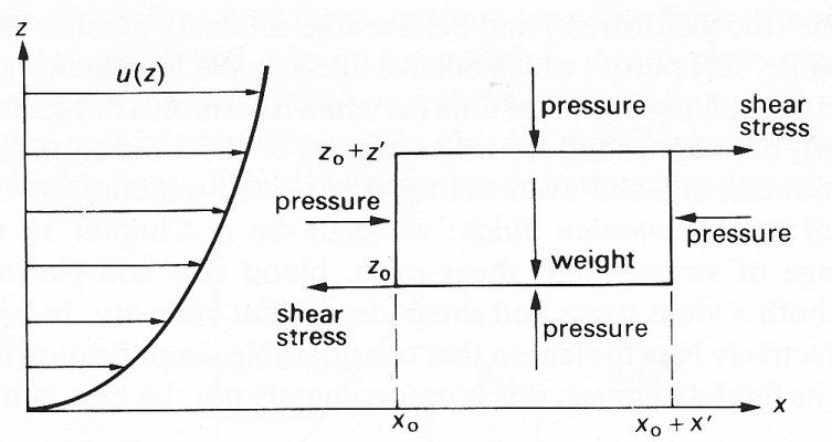
Fig. 4.5. The forces acting on a rectangular fluid element in a flow where the velocity u(z) is in the x-direction and varies only with z. The vertical force balance shows that the pressure at a particular value of x varies with height (z) as in a fluid at rest (Equation (4.1)). The forward shear stress (m du/dz) is smaller on the upper surface (z=z0+z') than the backward shear stress on the lower surface (z=z0) because of the shape of the graph of u against z. Therefore the pressure on the left-hand face (x=x0) must exceed that on the right-hand face (x=x0+x'), i.e. a negative (favourable) pressure gradient is acting on the fluid.
Gravity acts downwards (in the negative z -direction) and there is no variation of pressure or velocity in the third (y)-direction. The balance of forces in the vertical direction shows that the pressure at a particular value of x varies with height as in a fluid at rest, and is given by Equation (4.1). Now consider the horizontal force balance (per unit length in the y-direction). If there were no motion, there would be no viscous stresses, and the pressure on the left- and right-hand faces of the element (at x = x0 and x = x0 + x' respectively) would be equal. When there is motion, viscous forces do act; in the case shown, they tend to slow the element down, because the backward shear stress on the bottom surface of the element (at z = z0) is greater (because the shear rate du/dz is greater) than the forward shear stress on the top surface (at z = z0 + z'). If the pressures on the vertical faces were equal, the fluid element would therefore decelerate. The only way for the motion to be maintained, let alone accelerated, is for the pressure on the left-hand face to exceed that on the right-hand face. That is:
p(x0) - p(x0 + x') > 0
In other words there is a negative gradient of pressure in the x-direction;* [*The pressure gradient is defined as the slope of the graph of p against x, and so is the limit of the quantity {p(x0+x') - p(x0)}/x' as x' becomes very small. In other words it is dp/dx (see §2.2, for a discussion of this limiting process).]a negative pressure gradient is favourable to flow, while a positive one would be adverse. Unless there are body forces driving the motion, a favourable pressure gradient is required to accelerate a fluid or maintain its motion against the action of viscosity. For example, fluid can flow steadily along a horizontal pipe, in which the component of body force (gravity) in the direction of motion is zero, only if the pressure at one end is greater than that at the other.
For general flows, then, the equation of motion of any fluid element (i.e. Newton's second law) may be written in the form:
mass x acceleration = body force + pressure gradient force + viscous force. (4.5)
Since we know the relationship between viscous forces and the local variations in fluid velocity (shear stress is proportional to shear-rate), this equation relates the pressure gradient and body force at a point to the local fluid velocity and its rates of change with both time (acceleration) and position (shear-rate). The aim of theoretical fluid mechanics is to deduce the motion of every fluid element from this equation, and from the other known constraints on the flow, like the no-slip condition at a solid wall, or the constant pressure condition at a free surface exposed to the atmosphere. This can usually only be done in an approximate way, although there are certain restricted situations in which an exact theory is possible. The terms on the right-hand side of Equation (4.5) all represent forces, while that on the left-hand side is the mass-acceleration term, representing the inertia of the fluid elements. If this term were taken over to the other side of the equation, with opposite sign, it could be thought of as another force, and in fact it is common in fluid mechanics to speak of it as the 'inertia force term'. However, it is important, as with 'centrifugal force', to remember that it represents mass x acceleration, not force.
If we wish to measure velocity components or pressure in a flowing fluid, we normally put our measuring instrument into the flow at a certain point, leave it stationary while the fluid flows past, and record how its output varies with time during the experiment. This procedure can be repeated with the device in different positions, and the way the flow changes from one region to another, where conditions may be different, can be observed. This is a different approach from that used in the mechanics of isolated particles (Chapter 2), in which individual particles are followed as they move from point to point. If the latter approach were used for fluid elements, continuously being deformed, the relationship between stress and shear-rate would be very complicated. It is therefore much simpler in theoretical work, as well as corresponding more closely with experimental technique, to use the former approach. There is, however, one disadvantage, which is that it is more difficult to write down the acceleration of a fluid element because the rate of change of velocity at a point represents the difference in velocity of two elements which successively occupy that point. The acceleration of a single element must also depend both on how the velocity at a point varies with time, and on how the velocity varies from point to point, since the same element successively occupies different points. Particles can have acceleration even when the velocity at every point is constant with time (and the flow is said to be steady), since they can move between points of different velocity. A good example of this is in the flow of water over a weir: fluid elements well upstream of the weir move extremely slowly, but they are accelerated as they approach it, and shoot over it very quickly, Nevertheless, the flow is still steady, because the fluid velocity at any point is constant. This contribution to tHe acceleration of a particle is called the convective acceleration (experienced as the particle is convected from point to point by the flow); the contribution from the time variation of the velocity at a given point is called the local acceleration. An example of an unsteady flow, in which the local acceleration is the more important contribution, is to be found in the flow of blood in large arteries (see (Chapter 12). It is the presence of the convective acceleration term which makes the equation of fluid motion (Equation (4.5)) very difficult to solve in general.
Before we discuss the detailed nature of the flow of fluid in given situations, in particular that of blood in the circulation, there are two further general principles which must be considered. The first states that mass cannot be destroyed or created (except where nuclear reactions take place, in which case mass can be converted into energy and vice versa), and is known as the principle of conservation of mass. It is physically very obvious, but it exercises an important constraint on the types of motion which can exist in any given flow situation. It implies, for example, that the same mass of fluid must flow out of a system of tubes as flows into it, unless either the density of the fluid inside increases (so that a greater mass can occupy the same volume), or the volume of the system of tubes increases through the expansion of flexible walls. Now, all real fluids are compressible (can change their density) to some extent, but liquids such as water and blood are far less so than gases, and it is often a very good approximation to treat them as incompressible. The approximation breaks down when the fluid speed approaches the speed of sound in the fluid, which is the speed at which small pressure changes are propagated through the fluid (not through the walls of the vessel containing the fluid; propagation through the walls is important in the circulation, as shown in Chapter 12 ). In the circulation the maximum blood velocities observed are well below 1 per cent of the sound speed, so from now on we shall treat blood as an incompressible fluid, and shall ignore any phenomena associated with its compressibility. Thus if blood flows in a system of rigid tubes, what goes in must come out; in particular, if a single tube has a cross-sectional area A which varies along its length (Fig. 4.6),

Fig. 4.6. Diagram of a tube, containing incompressible fluid, whose cross-sectional area A varies along its length; in consequence, the longitudinal velocity u (averaged over the cross section) also varies along its length. In a rigid tube the volume flow-rate Q (= uA) is uniform at any given time, even if it varies with time: that is, u1A1 = u2A2. In a flexible tube A can vary with time, and at any time (u1A1 - u2A2) is equal to the rate of increase of the shaded volume.
the speed of the flow at any time will also vary along its length. The product of the area A with the average longitudinal velocity u at the same cross-section is a constant, independent of which cross-section is chosen. This constant is the volume flow-rate Q through the tube: uA = Q.
Thus if a wide tube becomes narrower, the velocity of the fluid increases; if it becomes wider, the fluid slows down. If the tube were not rigid, the volume flow-rate would not necessarily be spatially uniform, because the cross-sectional area could be variable in time. For example, if the area of a segment of tube increases with time, more fluid must flow in than flows out, so that the values of uA at the two ends must be different (Fig. 4.6). Only in steady flow would the volume flow rate in a flexible tube necessarily be uniform.
The second general principle concerns the conservation of energy. In the absence of nuclear reactions, the total energy of a system is made up of mechanical energy (kinetic and potential - see §2.6) and of thermal energy (heat). The laws of thermodynamics state that the rate of change of the total energy of a system is equal to the rate at which applied forces do work on it. When there are no applied forces, the total energy is constant, i.e. energy is conserved, although in general it is possible for mechanical energy to be converted into heat (and vice versa), for example by the action of viscous forces (see §4.3). The principle of conservation of energy can be used to derive an important result concerning the steady flow of fluids in which the effects of viscosity are locally extremely small, and may be neglected. This is usually true far from solid boundaries. The absence of viscosity means that if there are no applied forces, mechanical energy is conserved, and is not converted into heat.
It is convenient here to introduce the idea of a streamline; this is an imaginary curve drawn in space at a given instant so that at every point it is parallel to the direction of motion (the velocity vector) of the fluid at that point. In a steady flow, where the velocity at a point does not change with time, the streamlines coincide with the paths followed by individual fluid particles. That is not true in unsteady flow because although a fluid particle always travels in the direction of the local velocity vector, that direction may change at a later time, and the streamline passing through the particle may not pass through the previous location of the particle. Consider a steady flow, and imagine a narrow tube drawn in the fluid in such a way that its boundary consists everywhere of streamlines. There is thus no component of velocity across the boundary, and the fluid flowing in the tube is constrained always to remain in it (Fig. 4.7). This 'streamline tube' then resembles a rigid tube of non-uniform cross-sectional area, with the difference that the walls are not solid, and the viscous no-slip condition need not be applied. Now suppose that the two ends of a finite length of the tube are at different levels, and the fluid is flowing up from level z = z1 at one end (where its velocity is u1, cross-sectional area A1) to level z = z2 at the other (velocity u2, area A2). The principle of conservation of (mechanical) energy can be applied to the fluid instantaneously occupying this finite length of tube, as it flows upwards for a short time. In words it says that the gain in kinetic energy (which is positive in Fig. 4.7
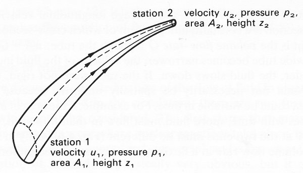
Fig. 4.7. Diagram of a stream tube, in a fluid in steady flow, whose long boundary consists everywhere of streamlines; no fluid crosses that boundary. The cross-sectional area A, height z, fluid velocity u, and pressure p are different at the two ends. The principle of conservation of energy shows that, when viscosity is unimportant, the quantity H (given by Equation (4.6)) is uniform (Bernoulli's theorem).
because the fluid is flowing towards a narrower piece of streamtube where, by the conservation of mass, the velocity is greater) plus the gain in potential energy (again positive in the case drawn because flow is upwards) is equal to the work done by the pressure forces on the ends (pressure p=p1 on end 1, p2 on end 2). The result of applying this principle is, in mathematical terms, that the quantity H], given by
H1 = p1 + 1/2ru12 + grz1
(where r is the fluid density), is equal to the quantity H2, given by the same equation with suffix 2 replacing suffix 1. If we define a quantity H, called the total head, by the equation
H = p + 1/2pu2 + grz, (4.6)
where p, u, z are the pressure, velocity, and height at an arbitrary point in the fluid, then the above result shows that H is constant along a streamline in steady flow (as long as viscous effects are negligible). The constant value of H in general varies from one streamline to another. The above result, known as Bernoulli's Theorem, could be deduced directly from the mathematical form of the equation of motion. Equation (4.5), in the same way as the equation of conservation of energy of a particle can be deduced from its equation of motion (§2.6). The consequences of Bernoulli's theorem in the circulation will be explored in detail later; however, as long as viscous effects are small (as they often are in large arteries; see Chapter 12), and if the flow is horizontal (i.e. z is a constant), then when the magnitude of the velocity u increases along a streamline, the pressure p correspondingly falls, and vice versa. The lowest pressures are associated with the highest velocities at a given level, in the same way as the lowest pressures are associated with the highest levels in a fluid at rest. Because changes in the terms 1/2ru2 and grz cause reciprocal changes in the pressure, these terms can be regarded as equivalent to pressures. The term grz is the hydrostatic pressure equivalent (or just hydrostatic pressure), and the term 1/2ru2 is called the dynamic pressure equivalent (or just dynamic pressure), since it is associated with motion.
In reality, all fluids have viscosity, which can cause mechanical energy to be irrecoverably converted into heat, or dissipated. The rate of increase of the mechanical energy of a fluid element is then equal to the rate at which work is done on it by the applied forces, less the rate at which mechanical energy is dissipated and becomes thermal energy. Far from solid boundaries, the effects of viscosity are small, and the total head H1 is approximately constant over short lengths of streamline. However, energy dissipation does occur, and a fluid element loses mechanical energy as it flows, experiencing a progressive (but gradual) decrease in the value of H with distance along the streamline. Over large distances this 'loss of head' can become appreciable. Mechanical energy is dissipated in all motions where frictional or viscous forces operate; another example is in the motion of a body on a rough surface (§2.6), where the dissipation occurs as the body does work against the frictional force, and the mechanical energy lost cannot be recovered. The heat produced by viscous dissipation in a fluid can itself have an effect on the fluid motion, by raising the temperature, and hence lowering the density, of some fluid elements, causing them to rise relative to other fluid elements. This phenomenon, called free convection, is not important in the circulation, because the temperature variations are not large enough (indeed, they cannot be measured).