The walls of blood vessels are elastic, and can change their size or shape when different forces are applied to them. These forces include both the pressures and shear stresses exerted by the blood, and the constraints imposed by surrounding tissue. In this chapter, therefore, we both outline the basic principles governing the mechanics of deformable solids, and show to what extent they are applicable to blood vessel walls, rather than leaving the application to a later chapter. The essentials of solid mechanics are of course contained in Newton's laws of particle motion; a solid material, like a fluid, can be thought of as split up into a large number of small elements, to each of which the laws can be applied. Again, the forces on the elements consist of long-range body forces and short-range stress forces; it is in the relationship between the stresses and the deformations of the material that solid and fluid mechanics differ.
We should begin with a few definitions. An elastic material is one which deforms when a force is applied to it, but returns to its original configuration, without any dissipation of energy, when the force is removed. This means that all the molecules return to their original positions. The first understanding of elasticity was obtained by Robert Hooke (the English astronomer and physicist) in 1678, from experiments with metal wires. In his experiments, a uniform cylindrical wire of unstretched length l0 and cross-sectional area A0 was suspended from a fixed support, and different weights W were attached to the other end (Fig. 7.1 (a)).
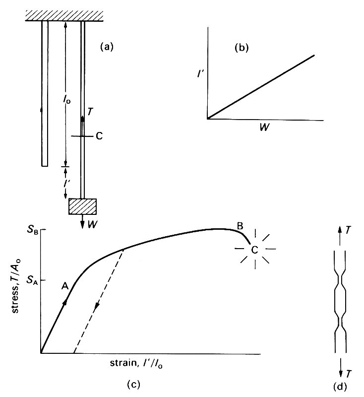
Fig. 7.1. (a) Hooke's wire-stretching experiment. A metal wire is stretched from a fixed support. When no weight is hung from it, its length is l0; when a weight W is hung from it, it is extended by an amount l'. C is an imaginary cut, used to define the tension Tin the wire, which is the force exerted by the upper piece of wire on the lower piece (or vice versa). A force balance on the lower piece shows that T must be equal to W.
(b) The results of an experiment like that of (a): extension l' is proportional to weight W, as long as W is not too large,
(c) The results of a complete wire-stretching experiment, expressed in the form of a graph of stress (= T/A0, where A0 is the initial cross-sectional area of the wire) against strain (=l'/l0). For stresses less than SA the two are directly proportional. For greater stresses, plastic flow takes place, which means that the strain does not reduce to zero when the stress is reduced to zero (dotted curve). Once the maximum applied stress SB has been reached, flow continues even when the stress is reduced below SB. Fracture occurs at C.
(d) Schematic side view of a wire in which necking has begun.
The extension l' was measured, and Hooke found that over a wide range of applied weights, the extension was proportional to the weight ('ut tensio sic vis') (Fig. 7.1 (b)). More recent experiments by, for example, Thomas Young (1773-1829: the English physician, physicist, and Egyptologist) have made this law (still called Hooke's Law) more precise, so that it applies to a series of wires with different cross-sectional areas, but all made of the same material. It is then found that the extension per unit length (I'/l0, usually called the longitudinal strain) is proportional to the tension T in the wire divided by the initial cross-sectional area A0. In order to define the tension in the wire we suppose it to be divided into two parts by an imaginary cut, marked as C in Fig. 7.1 (a). The total downward force exerted by the piece of wire below C on the piece of wire above C is then called the tension T. By Newton's third law, the upward force exerted by the upper piece of wire on the lower piece of wire also has magnitude T. Furthermore, if we consider the force balance on the lower piece of wire, we see that T must be equal to the weight W hanging from the lower end plus the weight of the lower piece of wire. In most experiments of this nature, the weight of the wire is negligible compared with W, so the tension T is equal to W. This result is true wherever the cut C is supposed to be, and the tension T in the wire is uniform along the wire. The tension per unit area T/A0 can be seen to have the form of a stress (see Chapter 4, §4.1); in fact it is the longitudinal normal stress exerted across any cross-section of the wire.
If Hooke's experiment were actually performed on a metal wire, with the widest possible range of applied weights, the graph of stress against strain would be as shown in Fig. 7.1 (c). (It is assumed that the experiment is performed statically, i.e. that there is no motion when the strains are measured.) The first part of the curve, up to the point A, is linear, showing that, for applied stresses up to SA, Hooke's law holds. Furthermore, the strain effectively reduces to zero when the applied stress is reduced to zero. For this range of stresses, the material is linearly elastic. If the stress is increased above SA, the stress-strain curve becomes non-linear, and, when the stress is reduced again to zero, a permanent deformation is observed which cannot be reversed; i.e. the strain does not return to zero (see dotted line in Fig. 7.1 (c)).
This indicates that there has been some flow. The stress SA above which this occurs is known as the yield stress; the flow is known as plastic deformation. Plastic deformation is irreversible in that, when it occurs, some part of the molecular lattice structure of the material is destroyed. As the stress is increased further, plastic deformation continues until the material eventually breaks on reaching the point C on the graph. After the maximum applied stress SB is reached, the material will continue to flow even if the stress is reduced somewhat. This is because, in this range of strains, the cross-sectional area of some parts of the wire is observed to diminish rapidly ('necking', see Fig. 7.1 (d)) so that the stress, measured as tension divided by undistorted area, is no longer a good representation of the actual stress, i.e. tension divided by actual area. The actual stress at the position where the area is smallest continues to rise from B to C.
The above description is still oversimplified, because if a stress in the elastic range (i.e. less than SA) were maintained for a very long time (several days in the case of steel wires), it would be observed that the strain very gradually increases. This implies that a very slow flow is taking place. If the stress were then removed, the strain would not reduce exactly to zero, but would still have a small value determined by the amount of flow which has taken place. This phenomenon is known as creep. It differs from plastic flow in that it is reversible: if a compressive stress were then applied for a long time, a reverse slow flow would be observed, and eventually the strain measured when no stress is applied could be reduced to zero. Creep does not irreversibly destroy the molecular structure of a material in the way that plastic flow does. The relative motion of neighbouring molecules resembles that in a viscous fluid, and can be reversed by reversing the applied stress. As in the flow of a viscous fluid, mechanical energy is dissipated during creep. An associated phenomenon occurs if, instead of holding the applied stress constant over a long time, we maintain a constant displacement for a long time. It is observed that the stress required to maintain it falls slowly from its initial elastic value. This phenomenon is called stress relaxation. Both creep and stress relaxation are examples of what is called visco-elastic behaviour. The fact that every material is viscoelastic to some extent means that no material is truly elastic in the sense of our definition. However, for very many materials, like steel in the wire experiment, or stone, or concrete, the amount of creep which occurs in the periods of interest is negligible, and they can be regarded as elastic materials for a wide range of applied stresses. As we shall see, the walls of blood vessels are visco-elastic, and this has a significant effect on the mechanics of blood flow within them.
Once an experiment, like the wire experiment, has been performed on a material, we can say that over a certain, known range of stresses (and times), the stress-strain curve is linear. In this range we can write
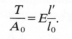 (7.1)
(7.1)
The constant of proportionality E is called the Young's modulus of elasticity of the material under investigation. E is a quantity characteristic of the material, and in the simplest materials is independent of the manner in which the stresses are applied; it has the units of stress, N m-2. Note that Equation (7.1) would apply equally well to the deformation of a cylindrical solid under a longitudinal compressive stress (like that applied to the tibia when one is standing upright or to a nail struck by a hammer); in that case both T and l' would be negative.
In the wire-stretching experiment already described, most materials experience a lateral contraction simultaneously with the longitudinal extension. For example, if the wire were circular, with undeformed radius a0, then, after stretching, its radius may be a0 + a', where a' is usually negative (Fig. 7.2; we keep to the convention of describing a contraction in length as a negative extension).
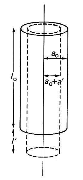
Fig. 7.2. Illustration of the reduction in a wire's radius (-a') which accompanies an extension in its length (l'). They are related by Equation (7.2).
For most simple materials, the lateral strain, a'/a0, is directly proportional to the longitudinal strain:
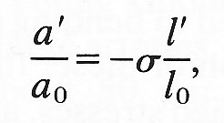 (7-2)
(7-2)
where s is another constant characteristic of the material called Poisson 's ratio (after the nineteenth-century French natural philosopher). The Poisson's ratio is a pure number (with no units) and is generally positive. If the volume of the circular cylindrical element of Fig. 7.2 does not change during a small deformation, then s must take the value 1/2. This is because the new volume p(a0 + a')2 (l0 + 1') must equal the old volume pa02 l0, and as long as a'/a0 and I'/l0 are
small, that requirement reduces to
which is Equation (7.2) with s = 1/2. In general, if a material is incompressible it has Poisson's ratio 1/2. In no material can it have a value greater than 1/2, since that would imply an increase in the volume of a cylinder after compressive stresses are applied to its ends. Almost all biological materials, in particular those comprising the walls of blood vessels, are effectively incompressible.
Equations (7.1)and (7.2) describe the response of a solid to a particular type of deforming stress, a longitudinal tension or compression, as long as it lies within the range in which the response is elastic. Like the equations governing the relationship between stress and rate of strain in a fluid, however, they can be simply generalized to cover small three-dimensional deformations.
In addition to longitudinal extension or compression, with the associated lateral strains (Fig. 7.2), a piece of material could be subjected to shearing stresses, which tend to cause layers of material to slide over each other (Fig. 7.3 (a)).
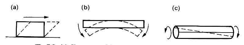
Fig. 7.3. (a) Shear stress, (b) Bending stress. (c) Torsional stress.
It could also be subjected to bending (Fig. 7.3 (b)), or torsion (twisting) (Fig. 7.3 (c)), or any combination of these. In each case, the strains would be directly proportional to the applied stresses, and the constants of proportionality could be expressed in terms of the Young's modulus E and Poisson's ratio s of the material. For an elastic solid of the sort described here (i.e., a metal), E and s completely determine the response.
We must now examine whether the materials comprising the blood vessel walls obey Hooke's law (stress proportional to strain), and, if not, how they depart from it. When classical elasticity theory is applied to a material, it is assumed that the material is effectively homogeneous and isotropic. That is, the values measured for E and s do not vary within the material (homogeneous) and are independent of the direction in which the stress is applied (isotropic). This means that, in whatever way a small specimen of the material is cut, and from whatever region, the same values of E and s are obtained in an experiment. Now biological tissues, in particular the walls of blood vessels, are neither homogeneous nor isotropic. They normally consist of a number of different materials, arranged in a complicated manner, which is described in detail in Chapters 12-15. We summarize here the properties of the most important materials.
About 70 per cent of the walls of arteries and veins consists of water, which is not elastic except in its ability to withstand compression. However, the rest of the material consists of a mesh of fibres which do have elastic properties. There are three sorts of fibres which determine the elastic properties of vessel walls as a whole: these are elastin, collagen, and smooth muscle. Elastin is a rubber-like substance, with a Young's modulus of approximately 3 x 10⁵ Nm-2; a graph of stress against strain for pure elastin fibres is given in Fig. 7.4 (a).
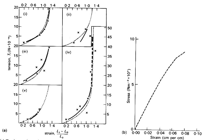
Fig. 7.4. (a).Tension-strain graphs of five fresh elastin fibres in Ringer-Locke solution at 37 oC. The measured points (x) are compared for each fibre with the individual regression curve (solid black) and the common regression curve (stippled). Ordinate: tension per fibre. Abscissa: strain (From Carton, Dainauskas, and Clark (1962). Elastic properties of single elastic fibres', p. 549, J. appl. Physiol. 17.)
(b) Graph of stress against strain for collagen fibres. (From Benedict, Walker, and Harris (1968). Stress-strain characteristics and tensile strength of unembalmed human tendon, p. 58, J. Biomech. 1.)
Collagen is much stiffer than elastin, with a Young's modulus of approximately 108 Nm-2; a stress-strain graph for collagen is given in Fig. 7.4 (b). Although elastin is so compliant that it can be stretched to twice its unstretched length, the value of the stress at which it eventually breaks (its tensile strength) is less than 5 per cent of that of collagen. Smooth muscle has a Young's modulus similar to that of elastin; however, the exact value measured in an experiment depends on the level of physiological activity. It varies from about 1 x 10⁵ Nm-2 when the muscle is completely relaxed, to about 2 x l06 Nm-2 in the active state. It is therefore difficult to say what its Young's modulus is in vivo, since the degree of activity is not usually known. In large arteries, at least those of dogs, elastin and collagen together constitute about 50 per cent of the dry mass. In the intrathoracic aorta the ratio of elastin to collagen is about 1.5, while in other arteries it is about 0.5; in veins it is as low as 0.3. Similar figures apply in man, although the transition to an excess of collagen over elastin occurs more peripherally, in the lower abdominal aorta. The amount of smooth muscle in an artery also depends on the position of the artery: the more peripheral it is, the larger its proportion of smooth muscle, which is about 25 per cent of the dry mass in the thoracic aorta, and reaches 60 per cent of the dry mass in very small arteries and arterioles. The basic structure of veins is similar to that of arteries, except that they are both thinner and contain less elastin.
The overall elastic behaviour of a blood vessel is determined by its dimensions as well as by the elastic properties of its constituent materials. The most important of these are the internal diameter d and the wall thickness h, which of course are different for different vessels. Typical values of these quantities in a number of different vessels, measured in vivo in dogs (or, in the case of very small vessels, in other mammals), are given in Table I at the front of the book. The table also contains much more information, which is pertinent to the various mechanical phenomena observed in the circulation, and this will be discussed in detail in subsequent chapters; we shall constantly refer to Table I. The quantities h and d both diminish towards the periphery. An interesting observation is that the ratio of wall thickness to diameter, h/d, does not vary very much throughout the large systemic arteries, having a value around 0.07. It increases in the more muscular arterioles, but is smaller again in the capillaries, and is much smaller in veins and pulmonary arteries than in the systemic arteries of comparable diameter.
An important constraint on the motion of blood vessel walls in response to the variable forces exerted on the inside of them by the blood is provided by the tissue through which they pass and to which they are attached. This has the effect of tethering the walls, and the mechanical properties of the tethering medium are significant (see Chapter 12). Capillaries, in particular, owe almost all their mechanical properties to the surrounding medium, because the wall itself consists of a single layer of endothelial cells.
Since the composition of blood vessel walls is not homogeneous, and since the material is arranged in such a way that it is most unlikely to be isotropic, classical elasticity cannot be applied directly and a single Young's modulus cannot be denned. However, it is still necessary to describe the response of the wall to different applied stresses, and a quantity like the Young's modulus would be very convenient for this purpose. What we do is to measure the deformation of the wall as a whole in response to known applied stresses, and to infer from those measurements the value which the Young's modulus would have if the material were homogeneous and isotropic. We lump together all the different constituent parts of the wall, and obtain an effective Young's modulus.
Two sorts of experiments have commonly been performed on excised arteries and veins. In one, a given length of vessel is distended by different, known, transmural pressures (the length being held fixed) and the changes in diameter are measured. As we shall see later (§7.3), a distending pressure in a blood vessel requires the presence of a tensile stress in the wall, directed round the circumference, which may be called circumferential stress or hoop stress (see Fig. 7.10 (b)). There will also be a longitudinal stress. The hoop stress is the stress from which, together with the change in diameter, E is inferred using Hooke's law (Equation (7.1)). In the other experiments, the piece of vessel is maintained at a given diameter, and stretched longitudinally, as in the wire-stretching experiment. Here the value of E is calculated from the longitudinal stress and strain. The results of such a pair of experiments on pieces of artery are shown in Figs. 7.5 (a) and (b).
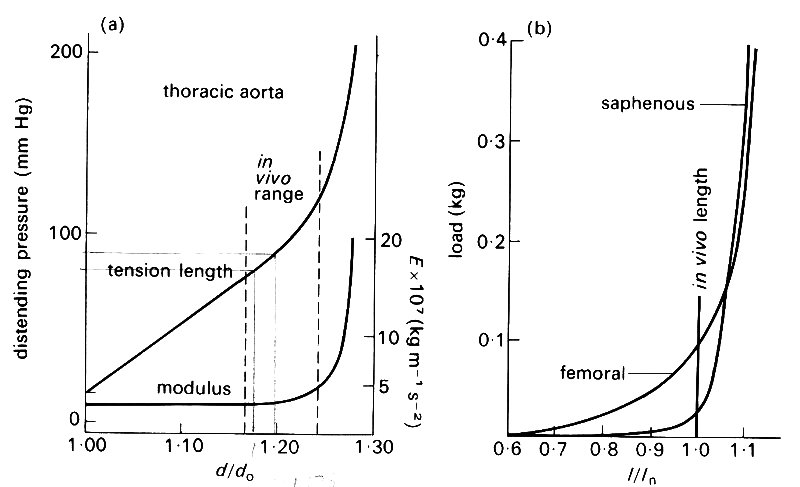
Fig. 7.5. (a) Graph of distending pressure against diameter for a piece of artery of fixed length; do = unstretched diameter. Note the non-linearity of the graph, on which the normal in vivo range is marked. Also plotted is the effective (incremental) Young's modulus E relating circumferential stress to circumferential strain. This increases dramatically for distending pressures greater than normal. (From McDonald (1974). Blood flow in arteries, p. 260. Edward Arnold, London.)
(b) Graph of longitudinal tension against length for pieces of two arteries of fixed diameter; /„ = in vivo length. Again note the non-linearity of the graph. (From McDonald (1974). Blood flow in arteries, p. 261. Edward Arnold, London.)
An obvious feature of these graphs is that, unlike those for metals (Fig. 7.1 (b)), they are not straight lines. So even when we lump all the components of the wall together, the linear relation (Equation (7.1)) is not apropriate, and we cannot uniquely define a Young's modulus. We can overcome this difficulty if we are interested only in small deformations about some equilibrium state. This need not be a completely unstretched state, because the tube may be already distended radially and stretched longitudinally. Let us suppose that there is an equilibrium configuration, in which the stress (either longitudinal stress or hoop stress) is S0 (Fig. 7.6),
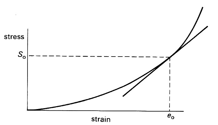
Fig. 7.6. Sketch showing the linearization of a non-linear stress-strain curve. For small departures from the equilibrium state in which stress is S0 and strain e0, the curve can be approximately represented by its tangent at that point; its incremental Young's modulus is then the slope of that tangent.
and the strain has a corresponding value eo. Then for small departures from this state, the stress-strain curve can be approximately represented by the straight line tangent to it at the point where stress equals So, and the small deformations can be analyzed in terms of a Young's modulus given by the slope of this tangent. The stress-strain curve is then said to have been linearized (see Chapter 8, §8.5). For example, let us consider a longitudinal stretching experiment in which small deformations take place about an initially stressed state with tension, length and cross-sectional area of the specimen equal respectively to T1, l1, A1. Equation (7.1) can still be used to determine an effective Young's modulus E if in its place we write
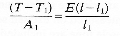
where T - T1 is the small increase in the tension and l - l1 is the small increase in the length. The value of E thus obtained is sometimes called the incremental Young's modulus. Its value clearly depends on T1, l1, A1, and it is always important to record the reference values at which E is measured.
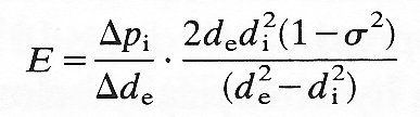
Now all blood vessels in vivo are tethered to the surrounding tissue, and are subjected to a considerable longitudinal stretch all the time: when a segment of artery is excised and released, its length decreases by 30-40 per cent. Furthermore the mean blood pressure in all arteries is considerably greater than that just outside: the excess is approximately 1.3 x 10⁴ N/m2 (100 mm Hg) at the level of the heart, increasing hydrostatically below that level, and decreasing above. Thus the arteries are naturally in a state of radial distension and of longitudinal stretch. The points representing the in vivo state are marked on Figs. 7.5 (a) and (b). It can be seen that the slope of the stress-strain curve, i.e. the incremental Young's modulus, is considerably greater at the in vivo state than in the unstretched state. Thus in order to analyse small deformations about the in vivo state we must use the correct incremental Young's modulus (this is also plotted on Fig. 7.5(a)). We shall see in Chapter 12 that the variable pressure and shear stress exerted by the blood do cause fairly small deformations of the wall about the stretched, in vivo state; they can be related to the variable stresses by use of the appropriate incremental Young's modulus. From now on, whenever a value of E is quoted for blood vessel walls, it will be the incremental value for the in vivo state. It will also usually be the value relating changes in diameter to changes in pressure (and hence hoop stress) rather than the value for longitudinal stretch. This is because the tethering inhibits longitudinal wall motions more than radial ones, and the latter turn out to be the more important.* It should be noted, however, that the Young's modulus for longitudinal stretch in an artery (calculated from Fig. 7.5 (b) for example) is usually different from that for circumferential stretch. This is a consequence both of the different initial stresses in the two directions, and of the anisotropic structure of blood vessel walls.
[*E is calculated from the equation
 (7.3a)
where Dpi is the change in internal pressure of the vessel, Dde is the corresponding change in the external vessel diameter de, di is the internal vessel diameter, and s is the Poisson's ratio, known to have the value 0.5.
If the vessel is thin-walled, its wall thickness h = 1/2(de - di) is small compared with di and di and de are approximately equal (and can be denoted by the same symbol d). In those circumstances, Equation (7.3a) can be reduced approximately to
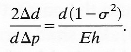
But 2Dd/dDp is equal to DA/ADp, where A is the cross-sectional area of the tube, and this quantity is defined as the distensibility D of the tube (see Chapter 12, §12.3.3). In the case of a material for which s2 is negligible compared with 1, Equation (7.3a) is approximately equivalent to
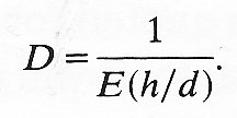 (7.3b)
The reason for the rapid increase in stiffness of blood vessel walls as their distension increases is thought to be associated with the different arrangement of collagen and elastin fibres within them. At low strains, most of the collagen fibres are slack, and not straight; all the stress is then borne by the elastin fibres. As the strain increases, the collagen fibres straighten out, and increasingly take up the stress. Since these are much stiffer than the elastin fibres (Figs. 7.4 (a) and (b)), the wall therefore becomes much stiffer. The situation is analogous to that of a balloon being blown up inside a string bag. It is relatively easy to start with, but extremely difficult once the bag is taut.
A further difficulty in applying elasticity theory to the walls of blood vessels lies in the fact that they exhibit significant visco-elastic behaviour (see §7.1). Steady deformations do not occur instantaneously when a steady stress is applied, but the immediate initial deformation is followed by a slower continuing deformation (creep) to an equilibrium value. Similarly the stress required to maintain a given deformation falls gradually from its initial value to a new equilibrium level (stress relaxation). It is thought to be primarily the smooth muscle which is responsible for the visco-elastic properties of artery walls, although collagen, despite its great stiffness, also exhibits visco-elasticity in experiments in vitro. Elastin, on the other hand, is known to be purely elastic; it is this elastic component in blood vessel walls which prevents creep or stress relaxation from continuing indefinitely. Visco-elasticity is important only when the stress or strain varies with time; for example, if a segment of artery is subjected to a cyclically varying strain of given frequency and amplitude, the stress required for a given strain is greater during extension than during recoil (Fig. 7.7). This phenomenon is an example of hysteresis.
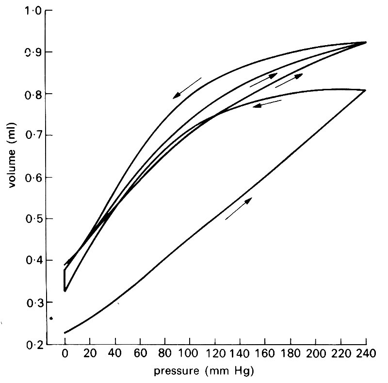
Fig. 7.7. Three consecutive pressure-volume curves of a femoral artery. The sequence of inflation and deflation is shown by the arrows (the last two deflations followed the same course). The vessel appears to become rather less distensible during the series of inflations. (From Bergel (1961). The static elastic properties of the arterial wall, p. 451. J. Physiol. 156.)
The properties of visco-elastic materials cannot usually be represented by a small number of constants in the way that linearly elastic materials can be represented by the Young's modulus and Poisson's ratio. Indeed, it is not usually possible to describe in exact mathematical terms how a visco-elastic material will respond to unsteady applied stresses of different kinds. And when it is possible, the mathematics is often so complicated as to be of little help. Sometimes, however, a simple approximate description of the behaviour of the material can be made, and is very useful. This is true of blood vessels when the deformations are small, and vary cyclically with time under the action of cyclically varying applied stresses (i.e. blood pressure and viscous shear stress, which vary with time during each cardiac cycle). The response of the strain to changes in stress is delayed slightly, so that as the applied stress varies cyclically, the variations in strain lag behind the stress, and have a smaller amplitude than they would have if the material were purely elastic (Fig. 7.8). (See Chapter 8, §8.1 for a precise definition of amplitude.)
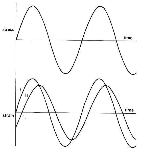
Fig. 7.8. When a cyclically varying stress is applied to a material, the resulting strain stays in phase if the material is purely elastic (curve I). However, if it has visco-elastic properties, the strain lags behind the stress, and varies with a smaller amplitude than if it were purely elastic (curve II).
It is possible to represent this behaviour by means of two constants, a 'dynamic Young's modulus' Edyn, and an 'effective viscosity' h. As we shall see in Chapter 8, §8.6, the variations with time of any cyclically oscillating quantity (the stress in this case) can be represented as the sum of a number of purely sinusoidal oscillations (Fig. 8.14, p. 128). If a single such oscillation in the stress has angular frequency w and amplitude S, then the corresponding oscillation in strain will have amplitude S/(Edyn2 + h2w2)-1/2, and the phase angle by which it lags behind the stress will be approximately hw/Edyn, measured in radians. Using these formulae, the values of Edyn and h can be inferred when a known, cyclically varying stress is imposed on a piece of artery, and the resulting time-varying strain measured.
Some results of such measurements are shown in Fig. 7.9.
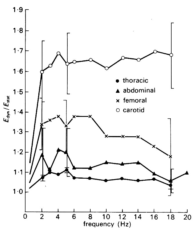
Fig. 7.9. Experimental plots of the dynamic Young's modulus Edyn, and the effective wall viscosity h times the angular frequency w against frequency (w/2p), for cyclic distension of pieces of arteries. Both Edyn and h w are approximately constant over a wide range of frequencies. (From McDonald (1974). Blood flow in arteries, p. 270. Edward Arnold, London.)
It is found that Edyn is usually greater than the value of E measured in static experiments. For frequencies below about 2 Hz (i.e. for w/2p less than 2 s-1), Edyn varies with frequency, approaching the static value as the frequency approaches zero. It is approximately constant for frequencies between 2 Hz and 20 Hz, and exceeds the static value by a ratio which varies from about 1.1 in the thoracic aorta of a dog to about 1.8 in the carotid artery. The viscous component h w also varies with frequency, but for frequencies above 5 Hz, the quantity h w is approximately constant and takes a value between 0.1 and 0.2 times Edyn The value of h w tends to be greater for smaller, more muscular arteries, which are therefore more visco-elastic.
In Chapter 12 we shall be concerned with the pulsatile motion of blood in large vessels, together with the movements of the vessel walls which take place at the same time. In other words, we shall examine the dynamics of blood and of vessel walls. First, however, it is necessary to look at the balance of forces exerted on the walls of a tube which is completely at rest and contains a fluid which is also stationary; i.e. we look at the statics of a vessel wall. Consider, for example, an artery, which is stretched longitudinally by the tethering forces, and distended by an internal pressure which exceeds the pressure outside (atmospheric pressure in many cases) by approximately l.3 x 104 Nm-2 (100 mm Hg), on average, at the level of the heart; it would vary between about 1.0 x 10⁴ and 1.6 x 10⁴ Nm-2 (80-120 mm Hg) during the cardiac cycle. We shall ignore gravity in the force balance; this is because when a blood vessel is distended by a large transmural pressure, the stress forces set up are very large compared with the gravitational forces. When the transmural pressure is not large, gravity can be important (for example, it can cause a thin-walled flexible tube in air to collapse), and in that case our conclusions would be strictly accurate only if the vessel were both filled and surrounded by a fluid which had the same density as itself; then the weight of the wall would be balanced by the hydrostatic pressure in the fluid. In the circulation there is an additional reason why gravity cannot always be neglected, since the pressure inside blood vessels varies hydrostatically (quite apart from the pressure variations associated with blood flow). For example, vessels in the foot will have an internal pressure which, in a man standing upright, can be greater than that at the level of the heart by about 1.3 x 10⁴ Nm-2 (100 mm Hg). In the head, the blood pressure is correspondingly smaller. The pressure outside blood vessels is approximately uniform, and close to atmospheric pressure except in the thorax where it can vary from about 3 x 10³ Nm-2 (23 mm Hg or 30 cm H2O) below atmospheric pressure to about the same amount above it during heavy breathing. Together with the fact that the transmural pressure varies between blood vessels of different types at the same level (being greater in arteries than in veins), this means that there is a wide variation of transmural pressure in the cardiovascular system. As we shall see, this proves to be important in determining whether or not certain blood vessels may be close to collapse.
Let us now examine the static balance of forces on a small element of the wall of a tube, neglecting gravity except in so far as it determines the pressure within the tube. We call the internal and external pressures pi and pe respectively, and suppose that the tube has a circular cross-section with internal and external radii ri and re (see Fig. 7.10 (a)).
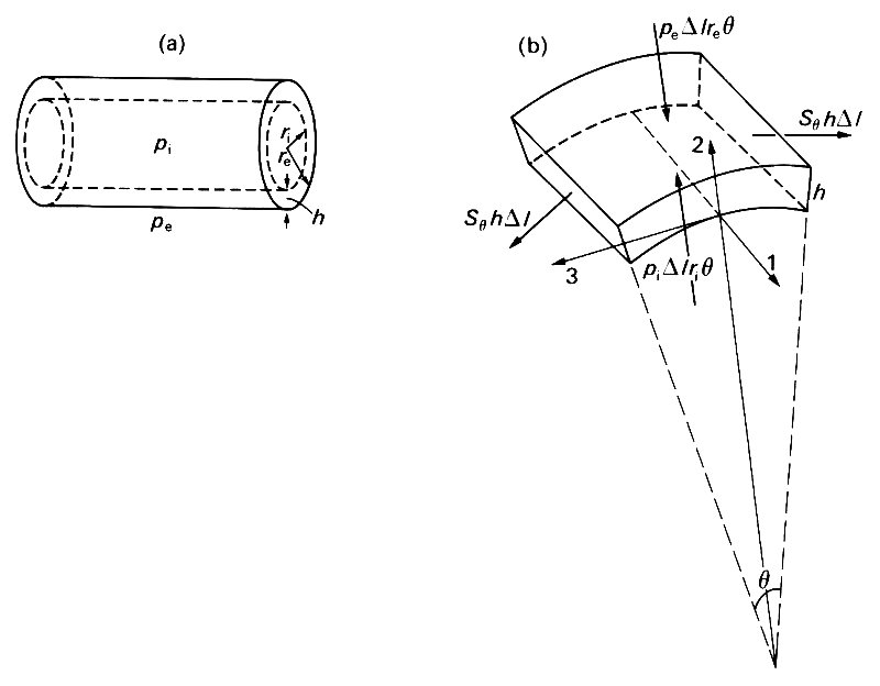
Fig. 7.10. (a) Sketch of a thick-walled tube, with internal and external radii ri and re respectively; wall thickness h = re - ri; internal and external pressures pi and pe.
(b) A segment of the wall of a thick-walled tube, of length Dl, thickness h, and subtending an angle q at the axis of the tube. The directions of the coordinate axes are parallel to the tube axis (1), radially outwards (2), and tangential to a cross section of the tube (3). The forces on the element are marked with heavy arrows; those on the curved faces come from the internal and external pressures; those on the flat faces parallel to the axis of the tube come from the 'hoop' stress Sq. The tensile forces on the flat ends balance out and are omitted.
The wall thickness h is equal to re - ri. We consider the equilibrium of an element of axial length Dl, subtending a small angle q at the axis (Fig. 7.10 (b)). The net forces on this element result from perpendicular (normal) stresses on its six faces; no tangential stresses can be present because of the symmetry of the arrangement. The net components of force acting on the element in three mutually perpendicular directions must be zero; we choose these directions to be parallel to the axis (1), radially out from the axis (2), and tangential to the tube in a plane perpendicular to the axis (3). The force balance in the axial direction (1) shows that the longitudinal tension T on each end must be the same (equal to the area of an end times the average normal stress over that end). Similarly the force balance in the tangential direction (3) shows that the normal forces on the two flat faces of the element parallel to the axis must also be the same (equal to the area of a face, hDl, times the average normal stress Sq over that face). However, because these faces are inclined to each other, and hence to the radial axis (2), they also have a component radially inwards, equal to 2 x Sqh Dl x sin 1/2q. The other contributions to the radial component of force come from the internal and external pressures; the outwards force from the internal pressure is pi times the area of the inner curved face (Dl ri q), and the inwards force from the external pressure is pe times the area of the outer curved face (Dl re q). Thus the radial force balance gives
![]() (7.4)
(7.4)
Now, when q is small, as we have supposed, sin 1/2 q is approximately equal to 1/2 q (that is accurate to within 1 per cent for values of 1/2 q up to 0.24 rad, or about 14°). We can therefore cancel out Dl q on either side of Equation (7.4), and are left with
![]() (7.5)
(7.5)
Sq is the average circumferential or hoop stress in the wall of the tube; the quantity Sqh is the total tension applied in the circumferential direction in the wall, per unit length of tube.
From our everyday experience with balloons, we intuitively expect a distension, caused by an excess of internal over external pressure, to be associated with tension in the wall. That is, when pi exceeds pe, we expect the tension Sqh to be positive. However, we can see from Equation (7.5) that if the wall of a tube is thick enough, i.e. if re is greater than ri by a large enough amount, this 'tension' can be negative, even when pi exceeds pe. In other words there is a compressive stress in the wall. This conclusion is quite independent of the elastic properties of the wall material; they become important in estimating the effect which the compressive stress has on the shape of the tube cross-section, as we shall see in §7.3. First, though, let us calculate whether the hoop stress in blood vessels is a tension or a compression.
Consider, for example, an artery within which the pressure exceeds atmospheric by l.3 x l04 Nm-2 (about 100 mm Hg), and outside which the pressure is atmospheric (105 Nm-2). If it is like the dog's femoral artery, for example, whose properties are given in Table I at the front of the book, it will have an internal radius of 0.002 m, and wall thickness 0.0004 m. Then, from Equation (7.5), we calculate the wall tension Sqh to be negative (i.e. a compression); its value is about -14.0 kg s-2. If the internal pressure were greater, by only 50 mmHg (as in the foot, perhaps) the wall stress would be a tension; if it were smaller, the compression would be more marked. In fact, if one calculates the wall stress in a great variety of blood vessels by this means, one concludes that the vast majority of them have a compressive hoop stress in their walls. The exceptions are the biggest vessels (aorta and vena cava), and other large vessels below the level of the heart, where the internal pressure is relatively high. The largest compressive stresses occur in small arteries and arterioles, whose walls are very thick, so that re exceeds ri by a large amount.
The fact that the underlying hoop stress may be compressive is not necessarily very important for the mechanical behaviour of blood vessels in vivo. This is because in the circulation we normally wish to analyse small departures from some equilibrium state. As we have explained earlier, it does not matter if there is some initial stress present in that equilibrium state or not, as long as the elastic properties of the material are represented by the effective Young's modulus, measured for small departures from the same equilibrium state. For this reason, it is common to quote values of tension and pressure relative to a given equilibrium state, and to ignore the absolute values. In physiology, we usually quote pressures relative to atmospheric. The corresponding tensions are quoted relative to their value when the pressures both inside and outside the tube are atmospheric: i.e. when pe and pi are both equal to patm. When that is the case, the hoop stress, say S0, is given by Equation (7.5) to be
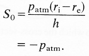
That is to say, all normal stresses are compressive and equal to atmospheric pressure. If, during a departure from this situation, pe remains atmospheric, if pi exceeds patm by an amount p', and if S0 exceeds (-patm) by an amount S', then Equation (7.5) can be used to give
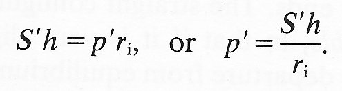 (7.6)
(7.6)
This is the well-known 'law of Laplace'. It shows that the pressure required to distend a tube against a given tension in the wall is inversely proportional to the radius of the tube. A balloon, for example, is more difficult to blow up when its radius is very small than when it is somewhat larger. In the circulation, the law indicates that, relative to atmospheric pressure, the tension required to balance a certain distending pressure decreases as the radius of the tube decreases. This is sometimes used to explain why the walls of capillaries can be so thin: they have only a small tension to support. However, that argument ignores the dominant tethering effect of the surrounding tissue, and may not be relevant.
The law of Laplace, then, can be used to analyse small departures from the equilibrium state in which all pressures are atmospheric. It cannot be used to give an accurate description of the absolute stress level in a vessel wall, unless the distending pressure is so large that the stress S0 (Equation (7.5)) is large compared with atmospheric pressure. This is usually not the case. If we come to analyse when vessels are likely to collapse, it is important to know the absolute stress level. By collapse of a vessel, we mean a drastic decrease in its cross-sectional area, which occurs spontaneously in response to a small change in applied stresses. It would also usually involve a change in cross-sectional shape, which may go from the circular to the elliptical or to more complicated shapes (Fig. 7.11). A tube will clearly collapse if the pressure outside it is very much greater than the pressure inside. The reason for the collapse is associated with the large compressive circumferential stress which, from Equation (7.5), must accompany such pressures. The phenomenon is similar to that of a straight rod which buckles (i.e. bends or crumples) when sufficiently large compressive forces are applied to the ends. The straight configuration is still theoretically possible, but it is unstable, in that if it is very slightly disturbed from the equilibrium position, the departure from equilibrium grows rapidly with time. The buckled condition is stable. In an analogous phenomenon, a pencil can theoretically stand on its point, but it is unstable, since any small departure from that configuration grows rapidly, and it falls over. (When it is lying on its side it is stable.) Similarly, the circular configuration of a tube wall is unstable if there is a large enough compressive stress within it. The wall then buckles, to form a distorted shape (Fig. 7.11), which is stable; the tube has collapsed.
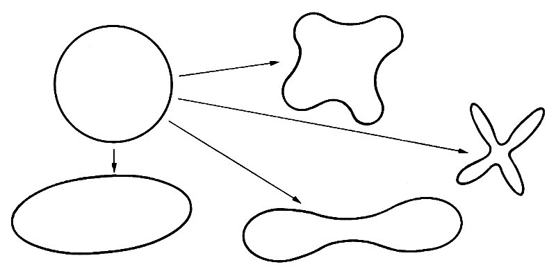
Fig. 7.11. Some of the shapes into which the cross-section of a circular tube might collapse.
The magnitude of the compressive stresses required for collapse, and the shape into which a tube collapses, depend on all the elastic properties of the wall. In particular, it is the degree to which the wall material can resist severe bending which governs the collapse, and this depends on the Young's modulus, Poisson's ratio, and wall thickness. The degree to which the tube is stretched longitudinally and tethered also influences its collapse. A very floppy tube with fairly thin walls under very little longitudinal tension collapses very easily, i.e. with a very small compressive stress in its walls. A blood vessel in vivo, however, is stretched and tethered and has fairly thick walls; collapse will be resisted. It is nevertheless observed that some veins and pulmonary arteries do normally have elliptic cross-sections, which indicate a degree of collapse associated with the compressive stress in their walls. Other situations where blood vessels collapse in vivo are considered in Chapter 14.